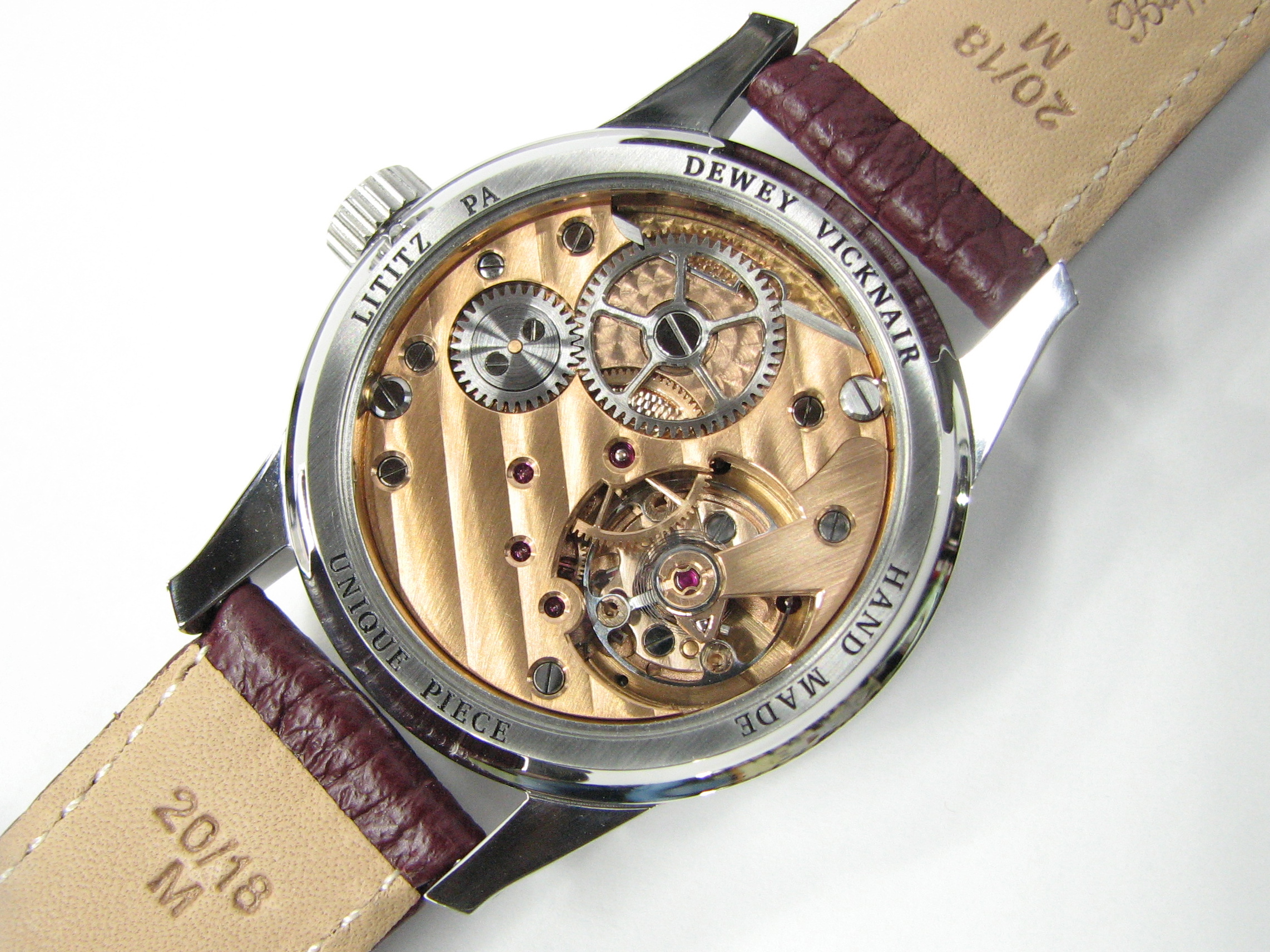
My second watch is a bit more ambitious of a project than the first one. Like the first one, the movement is based upon the Omega 266 but there is little left of it. It is a regulator display (hours, minutes and seconds separated) with jumping hours and a hacking (stop seconds) function for the seconds display and a free-sprung balance. The jump hours and hacking device are of my own design and, like before, everything is made by hand (my hand), from raw material to finishing and plating. The jump hours mechanism is built directly onto the main plate in order to minimize the increase in height, versus making an add-on module. It is housed in a stainless case made in the classic Calatrava style, 39 millimeters in diameter.
This post will be very heavy on photos (to silence the naysayers before they can speak up), so settle in.
PART 1: Making Parts
3/4 Plate:
We'll start with the making of the barrel and train bridge, which I decided to combine into a 3/4 plate. It is made from .125" thick 360 brass sheet. Most of the tools used in the construction of these parts were also made by me, including the sensitive uprighting drill press seen in the photos (which I will detail in another post).
Locating the steady pin and screw positions and cutting the screwhead counterbores


Turning the plate outside diameter


Turning the plate's thickness

Cutting the gear train pockets


The ratchet wheel pocket was also machined on the lathe

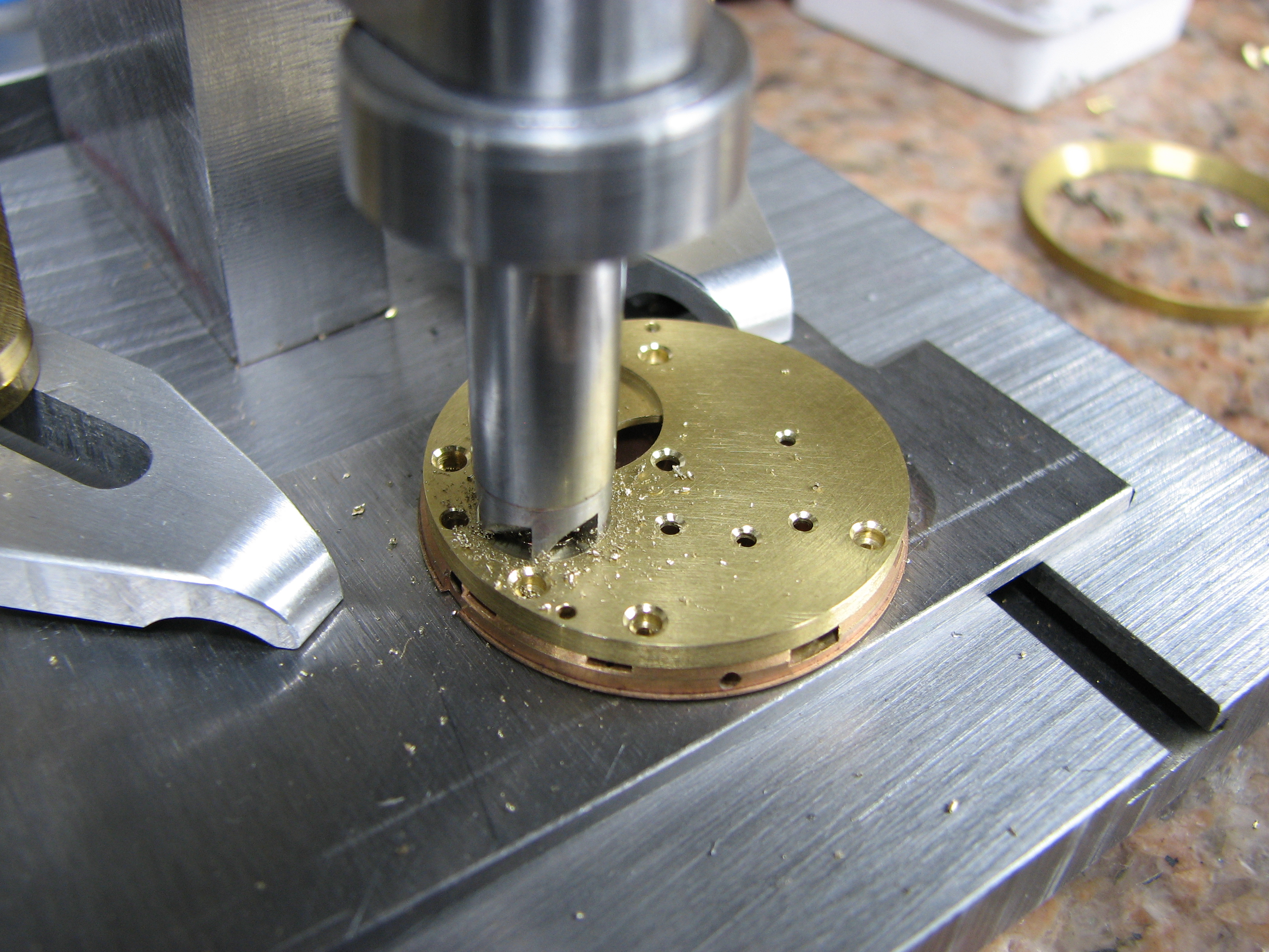
Cutting the well for the transmission wheel, which required annular cutters of two different diameters and a face cutter with a hollow center that would leave the center post standing. All cutters are shop-made.


Removing the balance wheel segment

The area around the escape wheel pivot is still rough

Machining the radius of the escape pivot


All of the inside corners are hand filed to remove the corner radii left by the milling cutter.


Machining the plates for the clickspring (the making of which will be detailed further on)


The pocket for the balance cock is cut away.

Reaming for the barrel arbor. The reamer is shop-made due to the non-standard diameter of the Omega 266 barrel arbor.

Face cutting to establish barrel endshake

Machining for the keyless works with cutters I made specifically for the job.


That about wraps it for the 3/4 plate (finishing will be detailed later), so let's move on to the balance cock, which is made in much the same manner as the previous part.
Balance Cock:
The 3/4 plate machined to accept the balance cock


Clickspring:
The clickspring is next. It is entirely filed by hand from 1095. The loop in the finished spring isn't ornamental but is a way of packaging a longer length of spring into a given space. As is common knowledge, all other specifications being equal, a longer spring is softer (has a lower rate) than a shorter one, hence the loop.
For a brief explanation of the particulars of different spring types, see here:https://vicknairgunsmithing.blogspot.com/2020/03/spring-has-sprung.html


Drilling the screw and steady pin holes and cutting the screwhead counterbore


Drilling the 3/4 plate for the screw and steady pin


Tapping the screw hole

Ready for heat treatment


After heat treating and repolishing the clickspring, the steady pin is pressed in place.


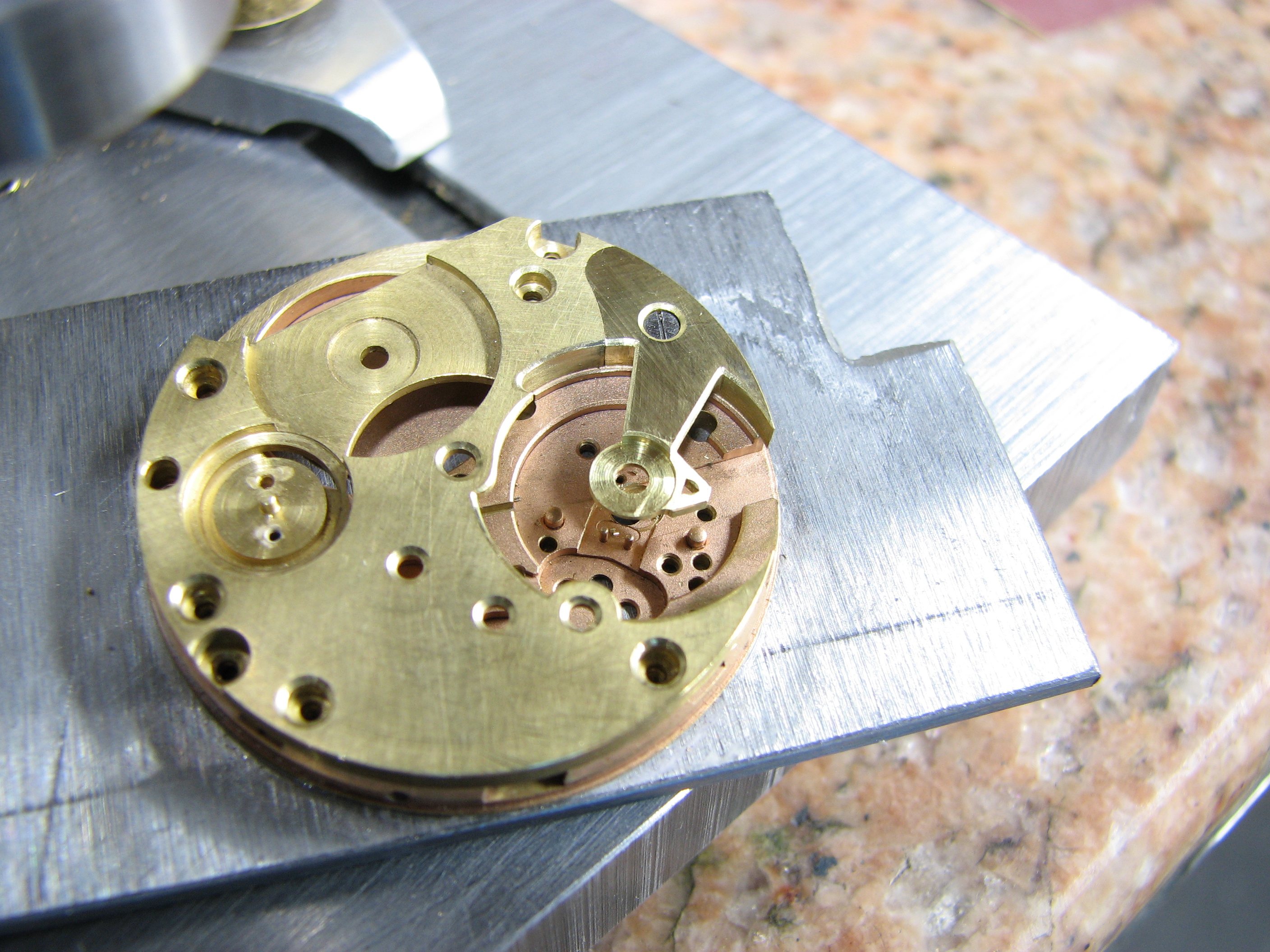
Though I started this post with the 3/4 plate, I actually started the project with the hacking mechanism. It is a simple one-part affair, that, rather than braking the balance wheel against the outer rim, brakes on the edge of the roller table. It operates in a linear fashion in a slot milled into the mainplate and is retained by the barrel bridge and the escape lever bridge. The tab engages the annular slot in the clutch gear, while the thin leaf at the opposite end applies the slightest friction to the roller table.


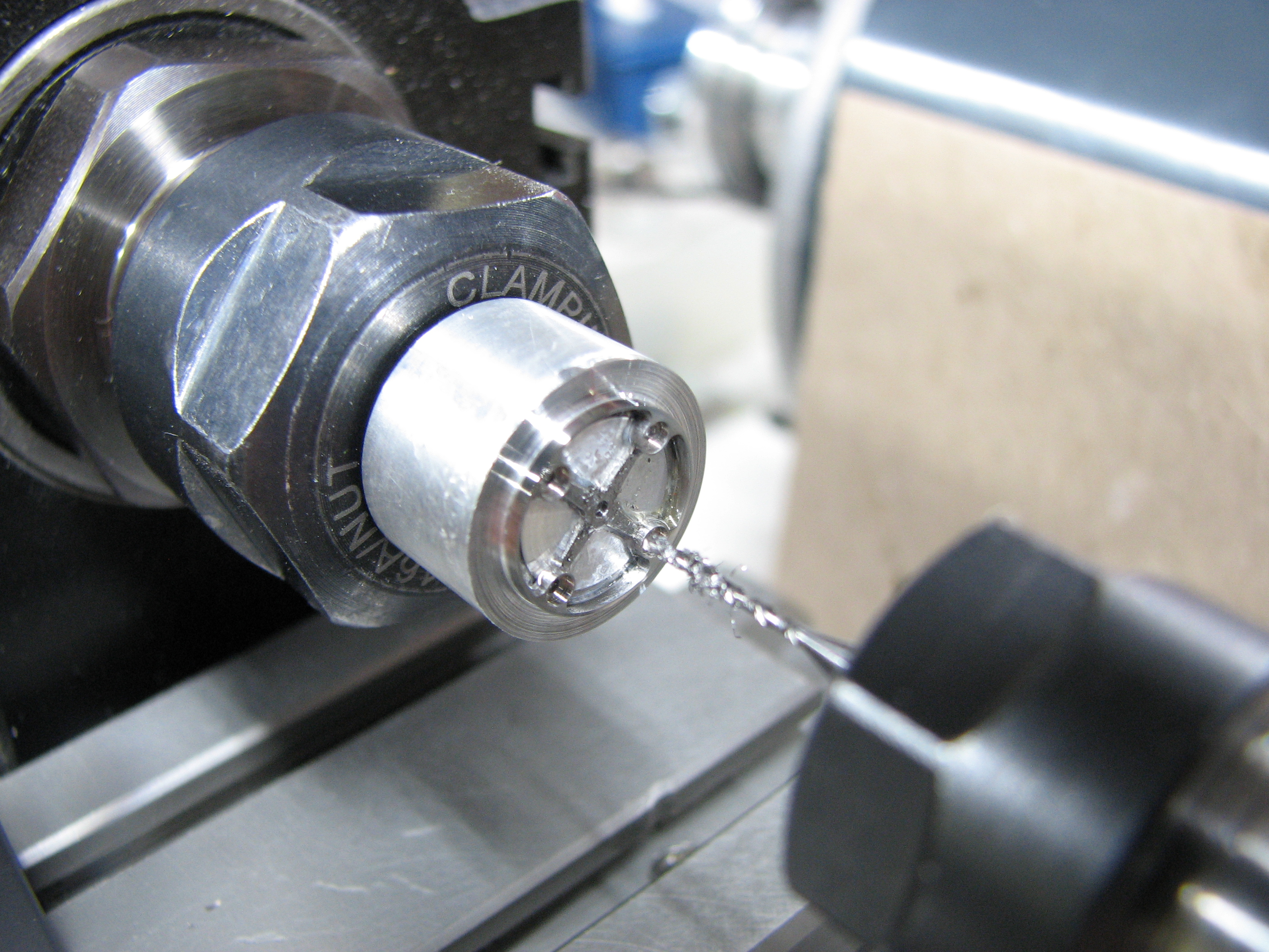
Balance Wheel:
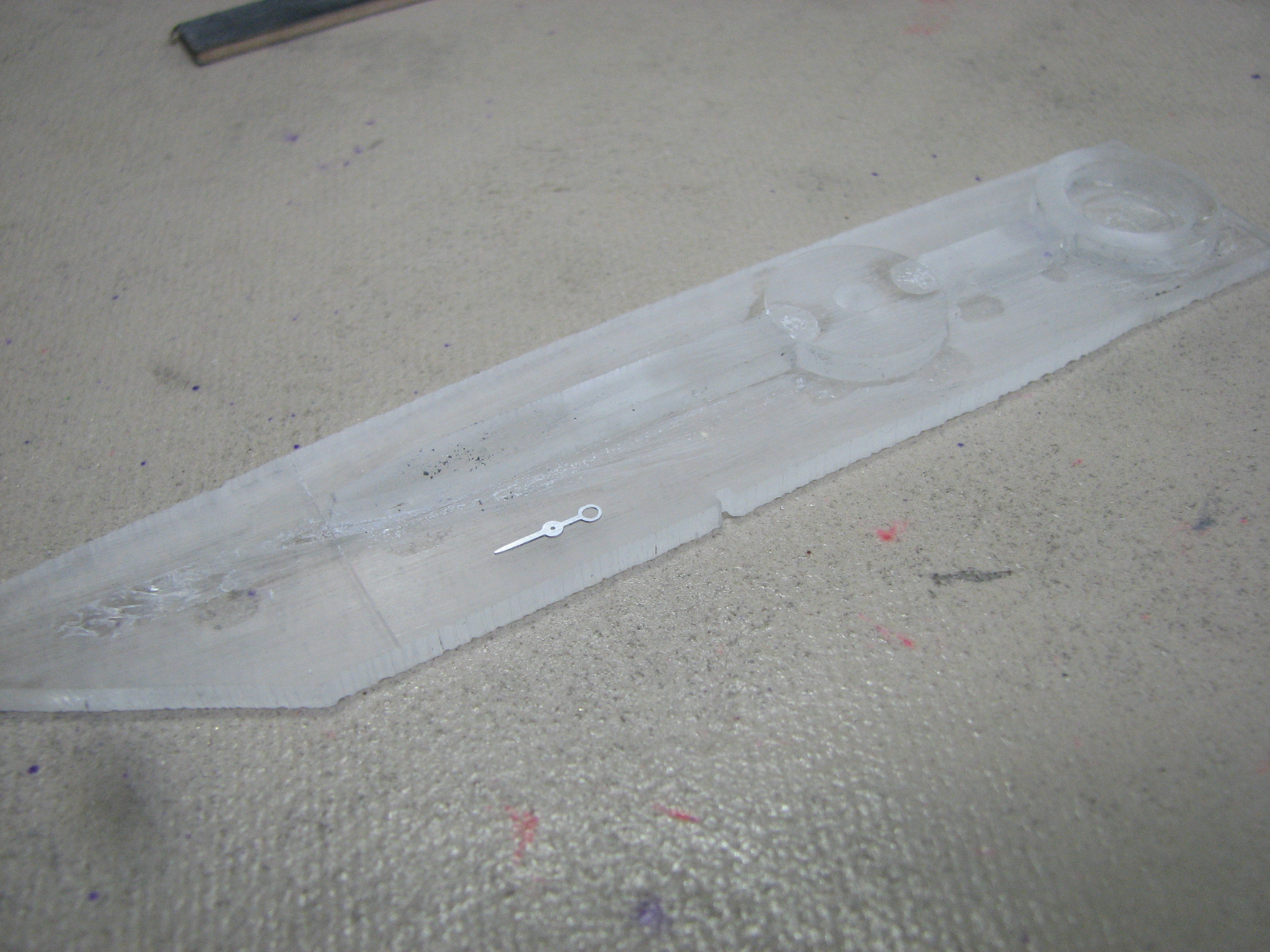
The balance wheel is made using the lathe, the pantograph and hand work. The oversized blank is initially turned and center drilled in the lathe, then the blank is mounted to the shop-made positioning table, which is itself mounted to the pantograph table. The spokes are cut on the pantograph, using the plexiglass pattern. The pattern is cut, then the positioning table is rotated 90 degrees (15 clicks) and the pattern is cut again. The inside corners of the pattern are still pretty rough looking but this is of no consequence, since the stylus used (.312" diameter with .0312" cutter) never reaches the corners. After machining the spokes, the balance wheel is dissolved from its holding fixture and cemented into the lathe chuck, so that the height of the wheel's center can be machined to size. The final outside diameter is also established at this time. The balance wheel is then again set up on the positioning table so that the pockets for the Gyromax-style weights can be machined. These pockets are made using a shop-made cutter.


Making the weights...


Staking the balance staff...


Poising (more details on the poising tool can be found in the tools post)...

We'll revisit the balance wheel in a bit.
Jump Hours Mechanism:
The jump hours complication is one of my favorites, but it's usually paired with a "digital" type display for the hours. Since the dial is in regulator format, where the hours are read first, I saw no reason that it could not be paired with a conventional hour hand. So, that's what I did. All pivots in the mechanism are jeweled in order to minimize friction. The photos document the mechanism, in its originally designed format and, after minor alterations, its final configuration.
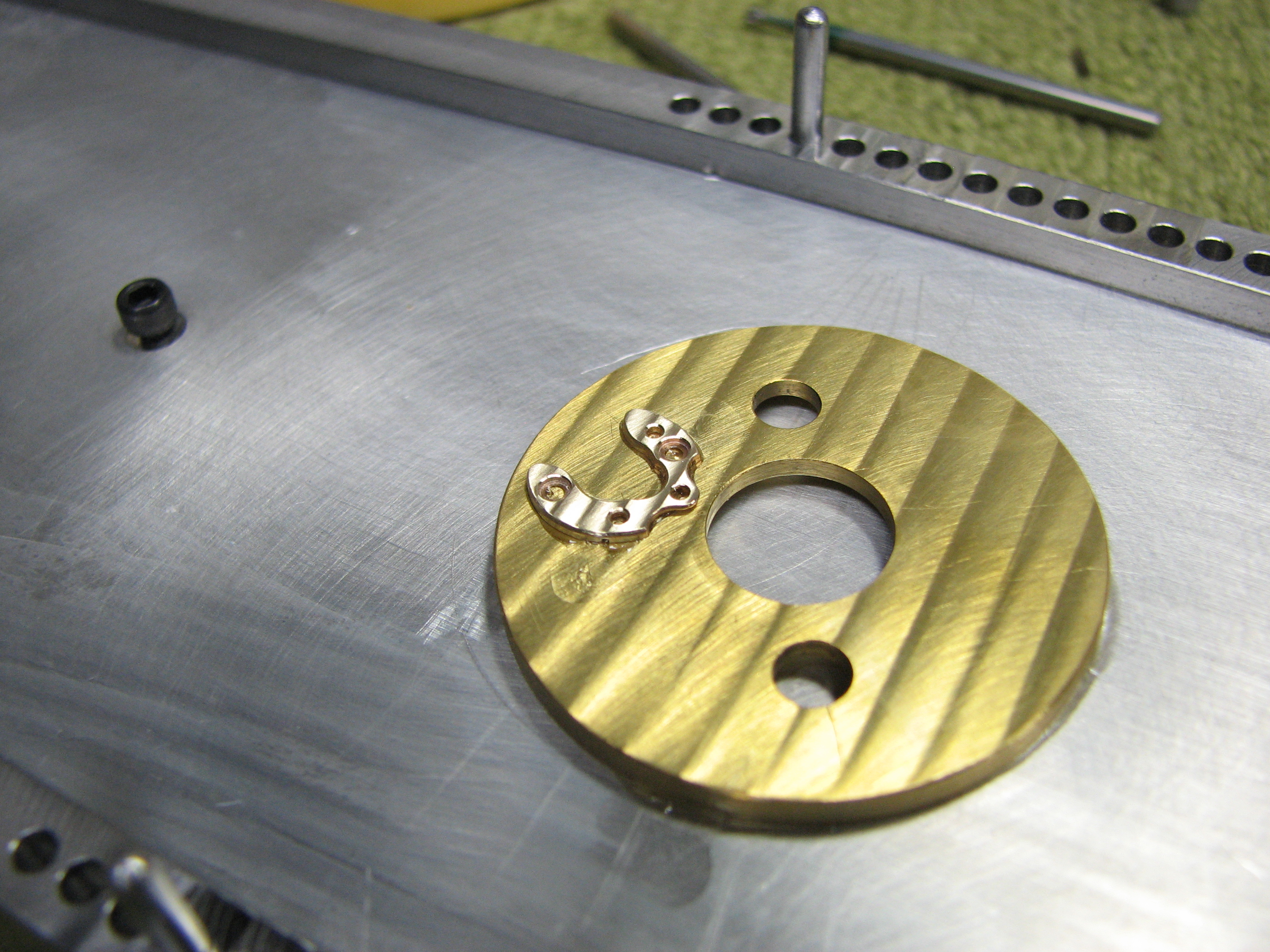
Making the star wheels...


The cocks for the star wheel train and the jump lever...


Making the jumper springs and lever...


The roughed-out jump train assembled. The configuration of the hour wheel lever would change in the final design.


Pressing the pivot into the new hour wheel lever...

I did not like the idea of having to continuously wind the minutes in order to set the hour, so I designed a "quick set" mechanism for the hours. It requires only that the crown be rotated back and forth, at the hour jump, to set the hour.


Here are a couple of videos. The more astute observer will note that I also jeweled the barrel arbor pivot.
Dial:
Let's move on to the dial (what there is of it at least)...
The photos are self-explanatory.


Hands:
The hands are made in two parts: the hand itself and a separate hub.


Finishes:


The case, caseback, bezel and crown are made from 316 stainless steel. Again, the photos tell all.


All I can say is WOAH!!!😳
ReplyDeleteVery impressive work, congrats!
ReplyDeleteIt's a real beauty, congratulations. You can be so happy and proud to own and create such a nice one off watch. It's not about money, it's all about having something unique, and made by your hands. Wish I could make my own watch. Paco
ReplyDelete